Got a working motor! (But not solar.)
I got to build a prototype motor! And it works.
There are so many open questions about the motor. How many magnets should the wheel have? Should it be an odd or an even number? What type of wire is best for the coil, and how many turns? I decided to first replicate something very close to the video I included in the previous post. That uses a reed relay, which is the simplest way to achieve motor control with zero electronics. Can I get a running motor from a battery? Will it run from a solar cell?
If you’re only interested in seeing the working proof-of-concept, here it is. For the part that really matters, read on ;-)

The frame
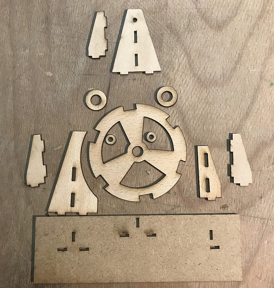
As a first step I need a test bed that lets me experiment and iterate on the unknown parameters. The point is to get it done fast, not to make it nice. Once I know what works and what the ideal position of each part is, I can go on and design something more fancy. I drew the SVG outlines, laser-cut the parts and the wheel, and glued things together. The images below should be give you an adequate idea of this straightforward structure. Key specs:
- Bottom plate is 3 mm MDF (fiber board). All other parts are 2 mm beech plywood.
- Magnets are 10×5 mm neodymium 1.33-1.37 T
- Ball bearing is 3×8×4 mm
Outlines of parts The parts, laser-cut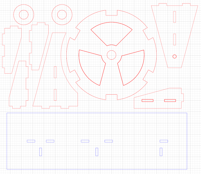
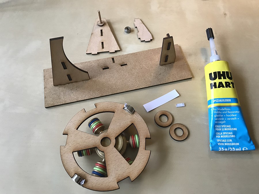
Building it all up
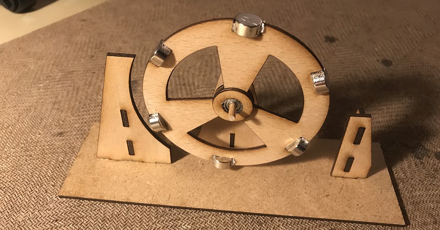
The built-up frame with wheel
The coil
I was, frankly, rather clueless about this part. The two key questions are: how thin should the wire be, and how many turns should the coil have? The fidget spinner motor from the last post’s video uses an 80-turn coil with Ø0.4 mm wire, but a different motor from the same guy uses a coil with 800 turns of Ø0.31 mm wire. There’s an entire literature about this, but I didn’t want to spend hours on this one detail. My search came up with this StackExchange answer, pointing to this online calculator. There’s a different good breakdown here. Also, Josh, the Deconstructing Kitty guy who hacked a Maneki-neko with an Arduino, has a convincing-sounding theory about the key tradeoff:
So it seams that (ideally) every time we double the number of turns, we use 1/2 as much power to get the same field at the same voltage. Make sense?
Of course double the turns also makes the coil bigger, and the bigger the coil the farther away geometrically the average wire will be from the center. This is why you also want very thin wire – especially since the increased resistance of the thin wire is less important as the current goes down.
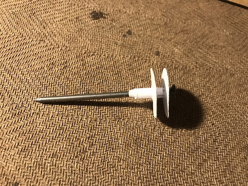
Eventually I said heck, you gotta make something, so I ordered a 110 m roll of Ø0.2 mm wire, started winding and waited to see how it goes. I improvised a bobbin using thick (200 g) paper and used a 3 mm thick nail to help me hold it while winding. I felt there were enough turns at 500, so that’s what my solenoid ended up having. At least I think it’s 500 turns: it’s really hard to keep track! I even had to take my loudly ticking clock out of the room because it messed up my counting.
Parts of the bobbin Ready for winding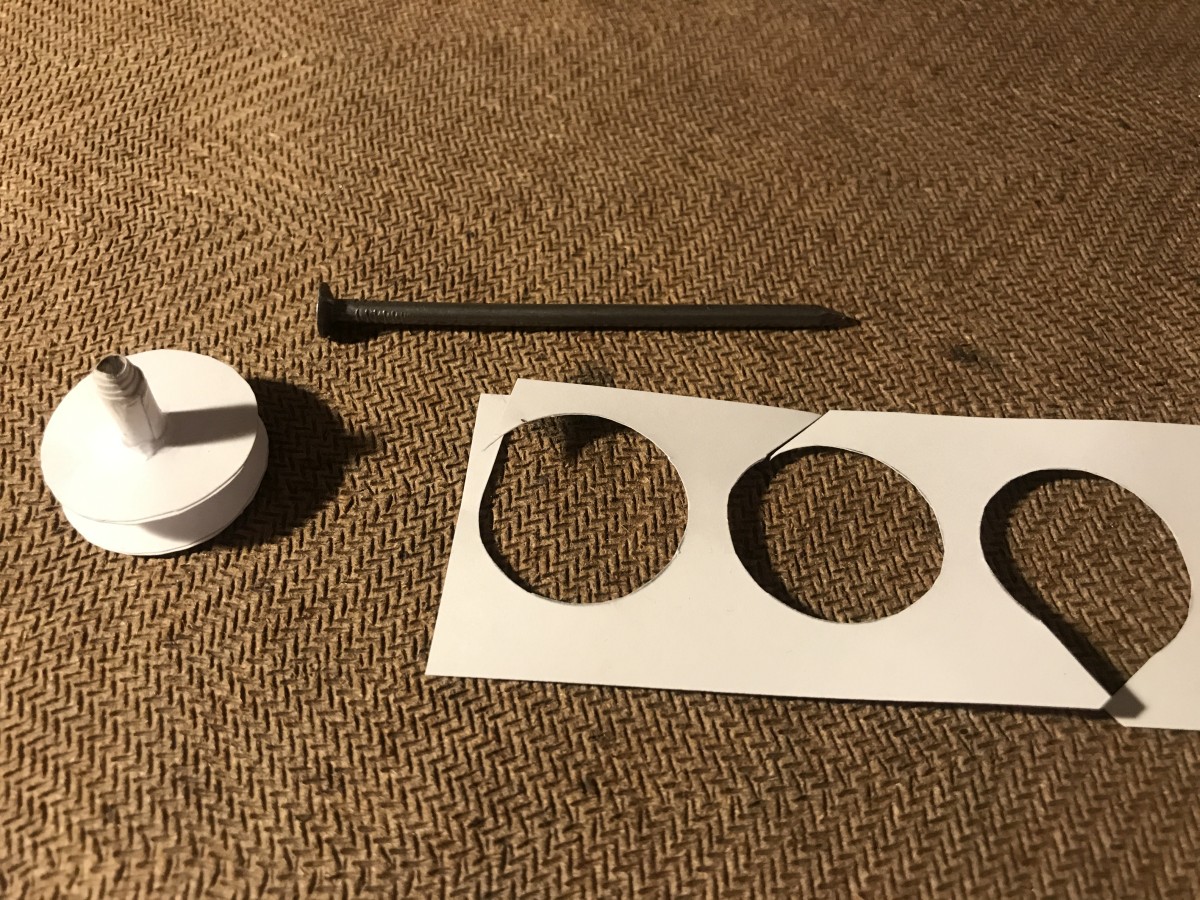
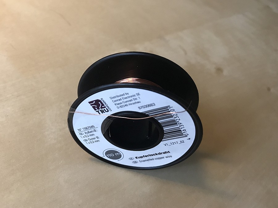
Wire
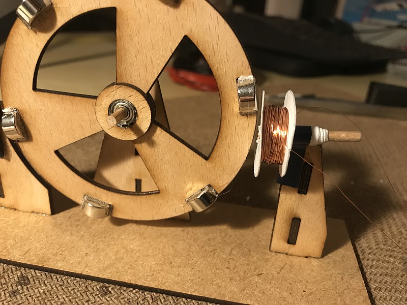
Finished coil in place
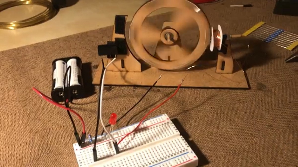
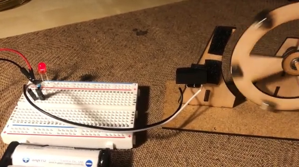
Reed relay control
What makes the wheel turn is that the coil is repeatedly activated for a short time at just the right moment, propelling the nearest magnet away from itself. This must happen right after the current magnet has passed in front of the coil, and it must not last too long, otherwise the coil will start repelling the approaching next magnet, slowing down the wheel instead of accelerating it.
The easiest way to achieve this is with a reed relay, which is simply two steel pieces (like two reeds) next to each other. The metallic reeds are apart when resting but close the contact when in a magnetic field. In other words, when a magnet is nearby, the reed relay closes the circuit and activates the coil. When the magnet is away, the circuit breaks and the coil is turned off. If you put the relay at the right spot near the wheel, it will keep activating the coil at the right moment and your brushless motor will run.
The video below shows the first half of this setup. The reed relay is the black part mounted on the frame (unfortunately hard to see clearly because it’s against a backdrop of black adhesive tape). For now, instead of the coil it is connected to an LED with a current limiting resistor. The blinking LED shows when the nearby magnet closes the relay.
The power comes from two NiMH AAA rechargeable batteries (2.4 V).
To be honest, I’m not even sure I want to use a reed relay in the actual forever engine. For one, I still consider it as a moving part, sort of. More importantly, to allow the microcontroller to count the wheel’s turns, I’ll need a different sensing mechanism anyway, which would add redundancy without any aesthetic purpose. So why did I use a reed relay now?
The reason is, this was the fastest way to get to a functioning initial proof-of-concept demonstrating that yes, I can build a working solar-powered motor. Which then takes me to the next point…
But it doesn’t work from a solar cell
After the initial joy at seeing the motor run from a 2.4 V battery I hooked it up to the intended solar cell, a 57×65 mm 5 V module rated at 81 mA.
Solar cell (front) Solar cell (back)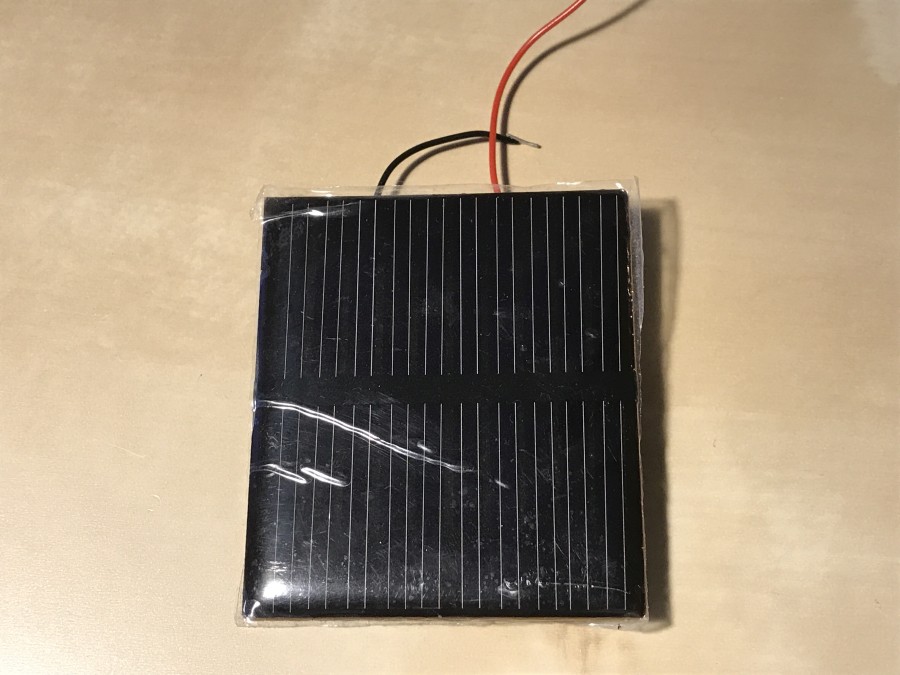
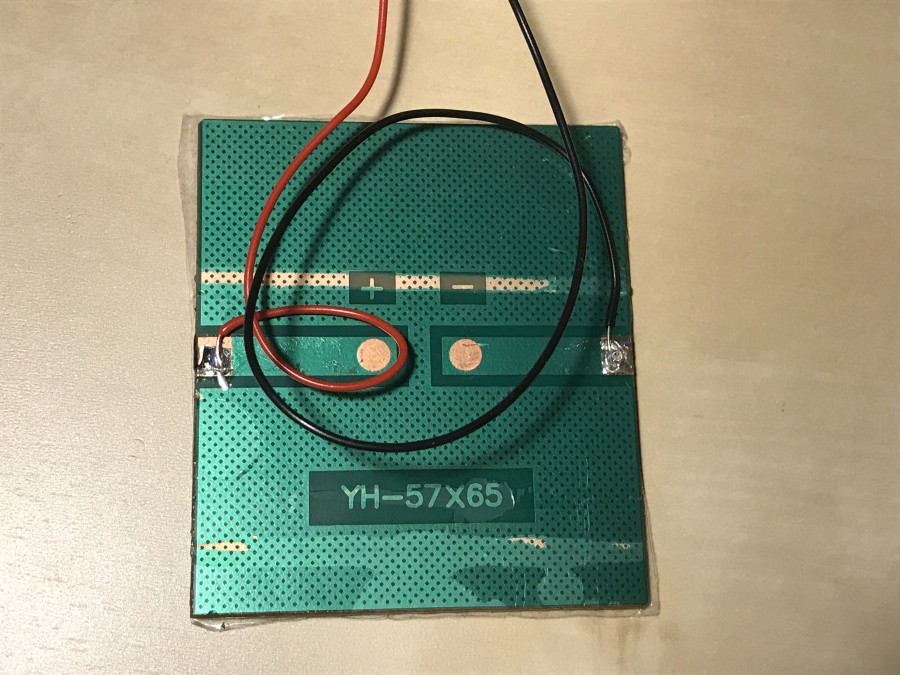
At this point my initial luck ran out. This solar cell was insufficient to get the motor running, at least when illuminated from a bright desktop lamp placed immediately against the panel. Getting to the bottom of this, however, will be the goal of another iteration.
Takeaways
-
These 10×5 mm neodymium magnets are really strong. Already when gluing them into the wheel, with the same pole facing inwards, you could feel how the last two or three were willing to either flip or get away outwards. And even the tiny amount of metal in the reed relay makes the wheel turn so the nearest magnet aligns with the relay.
-
Seeing how these magnets behave I also immediately got why the solenoid has no iron core. Just the presence of that core would attract the nearest magnet with overwhelming force.
-
With six such magnets placed in a Ø8 cm circle, the wheel’s angular momentum might be the main reason why the solar cell cannot supply enough power to move it. In other words, the things are just too heavy. Conclusion: I’ll be rebuilding the wheel with smaller, 5×2 mm magnets.
-
While I’m at it, I’ll also reduce the wheel’s diameter by maybe 2 cm. If you take a good look at the video you’ll see that the wheel needs a nudge to start: the nearest magnet is normally too far from the coil. Alternatively, maybe the engine will need a second coil at a 30° offset. What I’m not really eager to do is increase the number of magnets… 6 are already enough hassle to build up.
-
This is not very visible in either video, but the cheapo, no-name ball bearing I naïvely ordered from Amazon has a ridiculously large play. When the motor’s running it looks like a very beaten toy car’s wheel that’s just about to fall off. Here’s another brilliant yak shave: exploring the market of professional miniature ball bearings!
-
Finally, a fun fact about American engineering exceptionalism. Forget about Imperial units. For wires there’s an entirely separate system called AWG, short for American wire gauge, passed down to contemporary engineers straight from 1857! The larger the number, the thinner the wire. My 0.2 mm wire is apparently AWG 32.